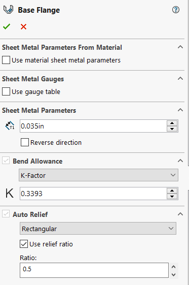
Relief Ratio Sheet Metal

Auto Vs Corner Relief In Solidworks Sheet Metal

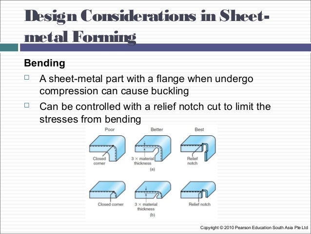
What S In Dfm Sheet Metal Design
2018 Solidworks Help Auto Reliefs

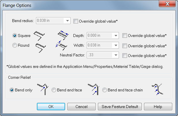
Sheet Metal Flange Features

How Sheet Metal Corner Reliefs Are Applied To The Body
Http Files Engineering Com Download Aspx Folder B0283dfb F6a8 4c7c 8207 Eb6510b27548 File Sheet Metal Design Considerations Pdf
Type smreliefcreate in the command bar.
Relief ratio sheet metal.

Bend Relief In Sheet Metal In 2020 Design Guidelines Sheet Metal Metal Design

Sheet Metal Design Guide Geomiq

Forming Basics For Sheet Metal Design

Bend Relief And Corner Relief Feature Operations Bricsys Support And Help Center

Working With Inventor Sheet Metal Styles
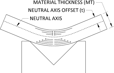
K Factor Sheetmetal Me

Sheet Metal Closed Corner Options Exposed

Mechanical Design Tutorial Sheetmetal Design
2017 Solidworks Help Creating A Corner Trim
2017 Solidworks Help Converting A Solid Part To A Sheet Metal Part

Creating Cuts Across Sheet Metal Bends Cad Booster
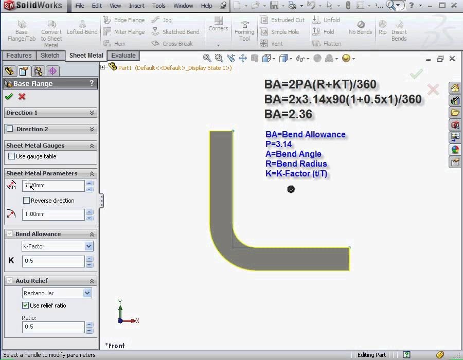
Solidworks Tutorials Sheet Metal 2012 What Is K Factor Youtube

Creating Three Bend Corner Reliefs Solidworks 2017 Youtube
How To Add Corner Reliefs In Solidworks Sheet Metal Models Youtube

Sheet Metal Fabrication Fundamental Cad Infield Fabrication Design
2020 Solidworks Help Creating A Sheet Metal Part Using Round Bends

Pdf Sheet Metal Design Handbook Vasu Mittal Academia Edu

Solidworks Material Archives
Https Encrypted Tbn0 Gstatic Com Images Q Tbn 3aand9gcsyli U0gftpsfsqaxjyymnyf8d4tkuo2xsqdknxb3v47 Lqlg Usqp Cau

5 Solidworks Tutorial Sheet Metal Solidworks Tutorial Solidworks Sheet Metal
Sheet Metal Processes
Sheet Metal Reliefs And Corners Solid Edge
Solidworks Sheet Metal Gauge Tables Perception Engineering
Http Staffweb Itsligo Ie Staff Sdalton Cad Pdf Sheet Metal In More Detail Pdf
Source : pinterest.com
